 MikeGrusin,
  bboyhoFavoritedFavorite17 ShareUse this URL to share: Share on Tumblr Submit to reddiShare on TwitterShare on Facebook Pin It Introduction
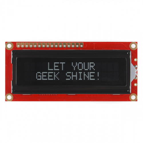
Printing data to a serial terminal is a great way to see data from a microcontroller. But, what if you want to make your project mobile and see sensor values away from your computer? Liquid crystal displays (LCDs) are a great way to output a string of words or sensor data to a display for visual feedback. In this tutorial, we'll learn about LCDs and how to print a string of words to a basic character LCD and create custom characters.
added to your cart!
Basic 16x2 Character LCD - White on Black 5V In stock LCD-00709This is a basic 16 character by 2 line display with a snazzy black background with white characters. Utilizes the extremely c…
$20.50 13 FavoritedFavorite22Wish List Required MaterialsTo follow along with this tutorial, you will need the following materials. You may not need everything though depending on what you have. Add it to your cart, read through the guide, and adjust the cart as necessary.

added to your cart!
SparkFun RedBoard - Programmed with Arduino In stock DEV-13975The SparkFun RedBoard combines the simplicity of the UNO's Optiboot bootloader, the stability of the FTDI, and the shield com…
$21.50 49 FavoritedFavorite95Wish List
added to your cart!
Breadboard - Self-Adhesive (White) In stock PRT-12002This is your tried and true white solderless breadboard. It has 2 power buses, 10 columns, and 30 rows - a total of 400 tie i…
$5.50 48 FavoritedFavorite102Wish List
added to your cart!
Break Away Headers - Straight In stock PRT-00116A row of headers - break to fit. 40 pins that can be cut to any size. Used with custom PCBs or general custom headers.
$1.75 20 FavoritedFavorite145Wish List
added to your cart!
Jumper Wires Standard 7" M/M - 30 AWG (30 Pack) In stock PRT-11026If you need to knock up a quick prototype there's nothing like having a pile of jumper wires to speed things up, and let's fa…
$2.45 20 FavoritedFavorite49Wish List
added to your cart!
Basic 16x2 Character LCD - White on Black 5V In stock LCD-00709This is a basic 16 character by 2 line display with a snazzy black background with white characters. Utilizes the extremely c…
$20.50 13 FavoritedFavorite22Wish List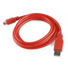
added to your cart!
SparkFun USB Mini-B Cable - 6 Foot In stock CAB-11301This is a USB 2.0 type A to Mini-B 5-pin cable. You know, the mini-B connector that usually comes with USB Hubs, Cameras, MP3…
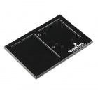
$4.50 3 FavoritedFavorite21Wish ListWhile not necessary, we'll be using a breadboard holder to hold the circuit together.
added to your cart!
Arduino and Breadboard Holder In stock DEV-11235We've been prototyping for a long time on these awesome little plastic plates but it's time for an upgrade. This version stil…
$4.95 13 FavoritedFavorite80Wish List
added to your cart!
SparkFun Mini Screwdriver In stock TOL-09146This is just your basic reversible screwdriver - pocket sized! Both flat and phillips heads available. Comes with pin clip an…
$1.05 3 FavoritedFavorite13Wish List Looking for More LCDs? There are a variety of other basic character LCDs with different colors. Here are a few other monochrome character LCDs available in the catalog. Just make sure to check the datasheet since the pinout for the backlight is slightly different for the RGB LCD.
added to your cart!
Basic 16x2 Character LCD - Black on Green 5V In stock LCD-00255This is a basic 16 character by 2 line display. Black text on Green background. Utilizes the extremely common HD44780 paralle…
$18.50 16 FavoritedFavorite21Wish List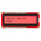
added to your cart!
Basic 16x2 Character LCD - RGB Backlight 5V 23 available LCD-10862This is similar to other 16x2 character LCDs that you've seen before but with one vibrant difference: The backlight is actual…
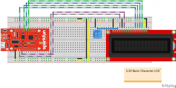
$18.50 3 FavoritedFavorite18Wish ListDepending on your LCD's specifications, the input voltage may be 3.3V or 5V. For the LCDs listed below, the input voltage for the LCD must be 3.3V. The logic levels will be the same as the input voltage.
⚡ Warning! When connecting to 3.3V basic character LCDs, make sure to connect the input to 3.3V.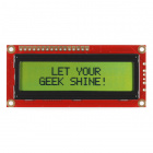
added to your cart!
Basic 16x2 Character LCD - Black on Green 3.3V Only 11 left! LCD-09053This is a 16 character by 2 line display that runs at 3.3V. Utilizes the common ST7066/HD44780 parallel interface ([datasheet…
$18.50 5 FavoritedFavorite8Wish List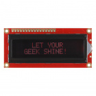 Basic 16x2 Character LCD - Red on Black 3.3V Retired LCD-09051
 This is a 16 character by 2 line display that runs at 3.3V. Utilizes the common ST7066/HD44780 parallel interface ([datasheet…
RetiredFavoritedFavorite7Wish List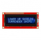 Basic 16x2 Character LCD - White on Black 3.3V Retired LCD-09052
 This is a 16 character by 2 line display that runs at 3.3V. Utilizes the common ST7066/HD44780 parallel interface ([datasheet…
3RetiredFavoritedFavorite13Wish List If you are using a 3.3V LCD and a 5V Arduino (or a 5V LCD and a 3.3V Arduino), you will need a logic level converter between the two boards. You'd have to use two logic level converters (like the four channel bidirectional logic level converter) to convert 6x pins at a minimum if you were using a 3.3V basic character display.
added to your cart!
SparkFun Logic Level Converter - Bi-Directional In stock BOB-12009The SparkFun bi-directional logic level converter is a small device that safely steps down 5V signals to 3.3V AND steps up 3.…
$3.50 120 FavoritedFavorite153Wish List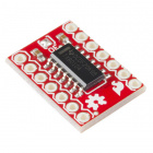
added to your cart!
SparkFun Voltage-Level Translator Breakout - TXB0104 16 available BOB-11771This is a breakout board for the Texas Instruments TXB0104 module. The TXB0104 is a 4-bit bidirectional voltage-level transla…
$4.95 8 FavoritedFavorite28Wish List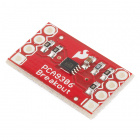 SparkFun Level Translator Breakout - PCA9306 Retired BOB-11955
 This is a breakout board for the PCA9306 dual bidirectional voltage-level translator. Because different parts sometimes use d…
3RetiredFavoritedFavorite12Wish ListToolsYou will need a soldering iron, solder, and general soldering accessories.

added to your cart!
Soldering Iron - 60W (Adjustable Temperature) In stock TOL-14456This adjustable-temperature soldering iron is a great tool for when you don't want to break the bank but need a reliable iron…
$16.50 16 FavoritedFavorite48Wish List
added to your cart!
Solder Lead Free - 15-gram Tube In stock TOL-09163This is your basic tube of unleaded (Pb-free) solder with a no clean, water soluble resin core. 0.031" gauge and 15 grams
$3.95 4 FavoritedFavorite15Wish ListSuggested ReadingIf you aren’t familiar with the following concepts, we recommend checking out these tutorials before continuing.
Binary Binary is the numeral system of electronics and programming...so it must be important to learn. But, what is binary? How does it translate to other numeral systems like decimal?FavoritedFavorite56What is an Arduino? What is this 'Arduino' thing anyway? This tutorials dives into what an Arduino is and along with Arduino projects and widgets.FavoritedFavorite56Installing Arduino IDE A step-by-step guide to installing and testing the Arduino software on Windows, Mac, and Linux. FavoritedFavorite17Logic Levels Learn the difference between 3.3V and 5V devices and logic levels. FavoritedFavorite89How Does an LCD Work?LCD stands for Liquid Crystal Display. These displays contain a grid of liquid crystal dots, or pixels held between layers of glass etched with transparent electrodes. Liquid crystal molecules are normally twisted, but straighten out when electricity is applied to them. This affects the way light passes through the dot, allowing it to appear either darkened or clear. A HD44780 controller chip built into the display (it's underneath the black blob on the back) receives commands from your a microcontroller, and turns the pixels on and off to form various letters, numbers and symbols. The controller datasheet has a diagram of all the characters stored in the chip. This display also has an LED for backlighting, which is powered usually through a basic character LCD pins 15 and 16.
If you look closely at the characters on the LCD, you will notice that they are actually made up of lots of little squares. These little squares are called pixels. The size of displays is often represented in pixels. Pixels make up a character space, which is the number of pixels in which a character can exist.
For more information on the history of LCDs and how they work, check out this video below.
Hardware Overview Note: Depending on how the LCD was manufactured, you may have a green or red PCB. Throughout this tutorial, you will see both colors but the overall functionality will be the same for a basic character LCD!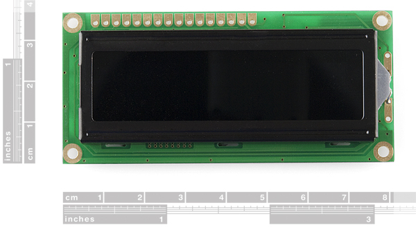
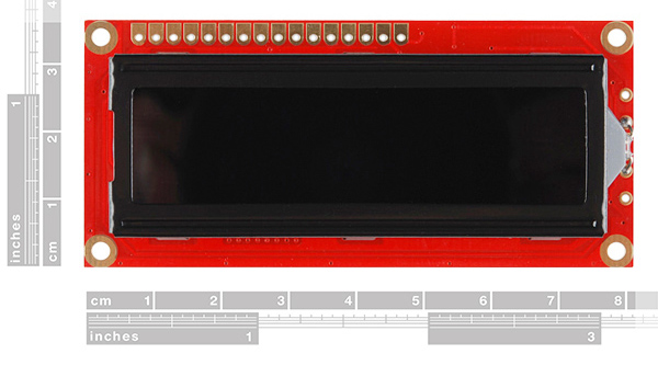 LCD w/ Green PCBLCD w/ Red PCB
 A basic character LCD has 16 pins (with the exception of an RGB LCD which has 18 pins), and it is polarized. The pins are numbered from left to right, 1 through 16. The LCD utilizes an extremely common parallel interface LCD driver chip from Hitachi called the HD44780. Thankfully, the Arduino community has developed a library to handle a great deal of the software-to-hardware interface. Below is a list of each of the pins on the LCD.
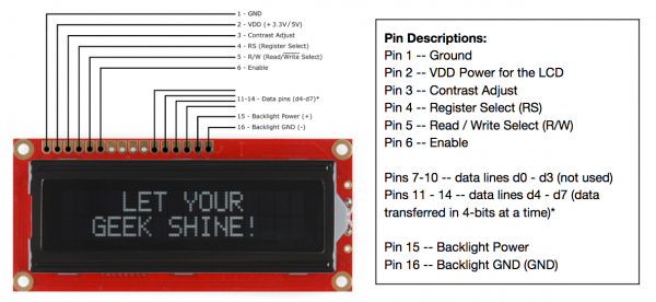 Click on image for a closer view. Input Voltage and Logic Levels
For the scope of this tutorial, we are going to be connecting a 5V Arduino to the 5V basic character LCD. Depending on your LCD's specifications, the input voltage may be 3.3V or 5V. The logic levels will be the same as the input voltage. Just make sure to match the voltages for the microcontroller and LCD.
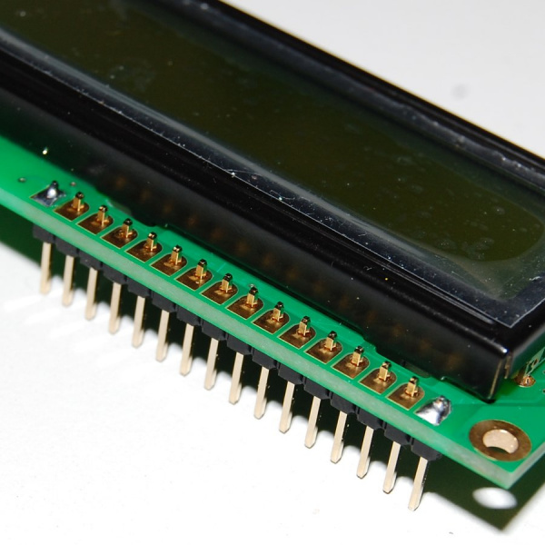
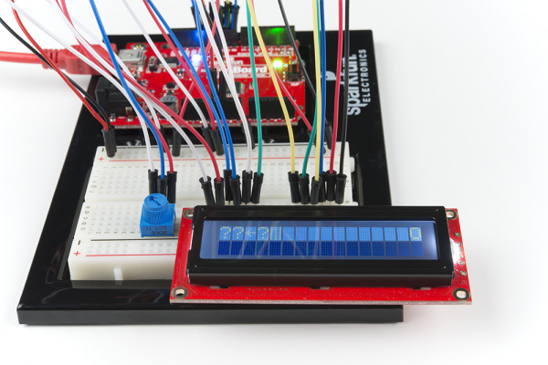
Hardware AssemblyLCDs usually come without a microcontroller to control the display. To connect, you will need a strip of header pins, a potentiometer to adjust the contrast of the display, breadboard, and wires. Depending on the LCD, you may need a current limiting resistor to to limit the current to the LED backlight. You will need to solder the header pins of your choice to the display in order to plug it into your breadboard. If you have not soldered before, we recommend looking at our soldering tutorial.
How to Solder: Through-Hole SolderingSeptember 19, 2013 This tutorial covers everything you need to know about through-hole soldering.FavoritedFavorite75While you can use any standard 16x2 alphanumeric LCD, the white on black display supplied with the kit looks übercool. The photographs in this guide are of a standard black on green display so yours may look different. The "16x2" refers to the display having two rows of sixteen characters each — other displays are available which are 8x1 or 20x4.
Soldering TipsIt is pretty straightforward to solder the header pins to the LCD module. Make sure to keep the soldering iron in contact with the joints for no more than about three seconds. There small risk of the damaging the existing components on the board with excess heat. You also need to be careful to keep the soldering iron away from the already soldered components on the board — you're probably not yet ready to do surface mount soldering repair.
Insert Headers to the LCDBefore soldering, perform a "test fit" of parts. A test fit gives you a chance to double check if you've got the parts you need and ensures that they fit together. For this connection, break a row of 16x1 male headers and insert the header pins into the holes on the LCD module as shown in the image below. If you are using an RGB LED, you will need a row of 18x1 male headers.
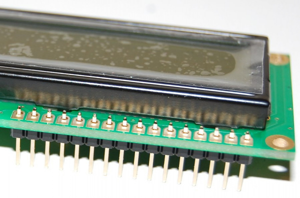
Ensure that you don't have one pin too many or too few in your header strip. Also make sure the black plastic strip of the header is positioned on the underside of the printed circuit board (PCB) so that you have plenty of pin length below the PCB to plug into your breadboard or a socket. The longest part of the pins should be below the PCB. The pin header provides connections that carry the data signals for controlling what the display... displays. They also carry power to the small microcontroller behind the black blob on the module and to the LED backlight if your display has one.
Soldering Male HeadersIf you've done a test fit then your header should be in place. Ensure the header is aligned as parallel as possible to the edge of the board. Then solder the far left or right pin into place as shown in the image below.
Because there's not a lot of room it is easiest to feed the solder from behind pin while the soldering iron tip is between the pins, resting on the PCB pad with the side of iron against the side of pin you're soldering. The reason we start with just one pin is because it makes it easier to obtain the correct alignment and fix any mistakes.
If the alignment of the header isn't quite right, carefully reheat the solder joint and move the header slightly. Don't move the header when the solder joint is still in it's liquid state however, or you'll end up with a poor joint.
Once you're happy with the alignment of the header you can solder another pin into place — we recommend soldering the pin at the opposite end of the header to the first pin you soldered. The reason for this is that once the two end pins are in place, the alignment won't change.
Double check the alignment is still okay and if it's not quite right you can reheat the joint and carefully move the pin. After you've confirmed the alignment, you can solder the remaining pins into place.
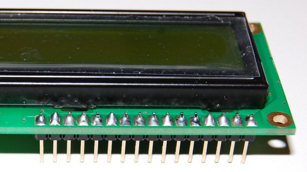
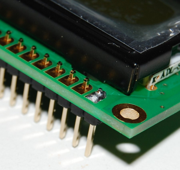
Ensure that the solder covers the plated through hole's pad and pins as shown in the image below for the best connection.
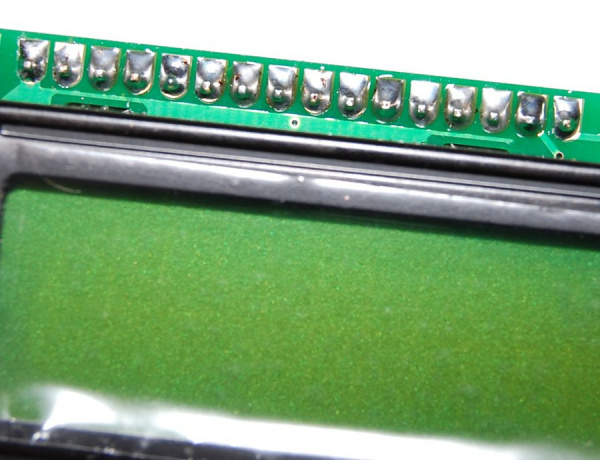
And now the soldering is complete!
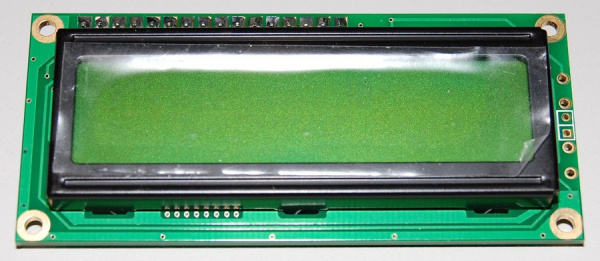
Completed LCDYour display module should now look like the image below. One additional detail to note is that the pin header is usually at the "top" of the display — so keep that in mind if you plan to mount it anywhere. Remember to always test the display out before mounting to a project.
Now it is time to connect your LCD to a microcontroller! For the scope of this tutorial, we'll use an Arduino.
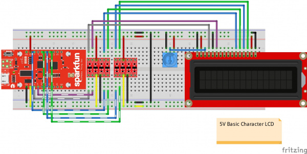
Hardware HookupThe basic character displays use a parallel interface, which can be either 4 bits or 8 bits wide. We'll use 4 bits, since it requires fewer wires. It will take a total of 8 wires to connect the display to your a microcontroller:
two for Vcc and groundtwo to load the datafour for dataYou will also need to connect a potentiometer to the display. This is necessary to set the contrast of the display for best visibility. See the following diagram for details.
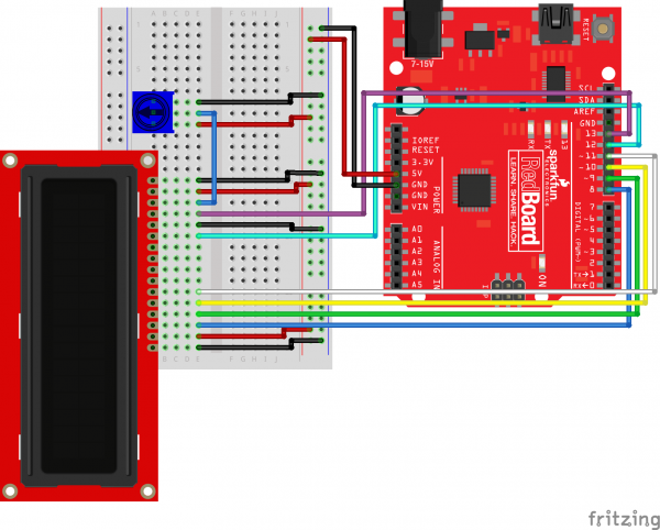 Note: Depending on the manufacturer, some LCDs may not come with a current limiting resistor for the backlight. You may need to add an additional current limiting resistor to control the backlight pin(s) from an Arduino's I/O pin. For more options controlling the backlight, you can connect the LED to any PWM pin. Depending on your microcontroller specifications, you may want to use a transistor to source enough current to an LED from an I/O pin.
added to your cart!
Resistor 330 Ohm 1/4 Watt PTH - 20 pack (Thick Leads)In stock PRT-14490These are your run-of-the-mill 1/4 Watt, +/- 5% tolerance PTH resistors. Commonly used in breadboards and other prototyping a…
$1.05 FavoritedFavorite12Wish List
added to your cart!
Transistor - NPN, 60V 200mA (2N3904) In stock COM-00521These are very common, high quality BJT NPN transistors made by ST Micro.
$0.55 FavoritedFavorite17Wish List RGB Backlight Note: If you are using the 5V basic 16x2 character LCD w/ RGB backlight, the LED's pins are slightly different. Pin 15 is for the LED's common cathode pin and it should be connected to the GND pin. Additionally, the LCD-10862 requires a current limiting resistor for each color. The diagram below shows a general 330Ω resistor in series.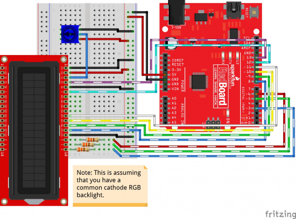 Arduino Examples: LiquidCrystal LibraryNote: The library has been tested on an ATmega328P-based Arduino using Arduino IDE v1.8.9. Otherwise, make sure you are using the latest stable version of the Arduino IDE on your desktop. If this is your first time using Arduino, please review our tutorial on installing the Arduino IDE. If you've never connected an FTDI device to your computer before, you may need to install drivers for the USB-to-serial converter. Check out our How to Install FTDI Drivers tutorial for help with the installation.
Normally, you would need to read the HD44780 controller chip's extensive datasheet to determine how to control this display. Fortunately, the Arduino IDE comes with a built-in library called LiquidCrystal, which does all the hard work for you. We'll look at one of the ten examples provided from Arduino.
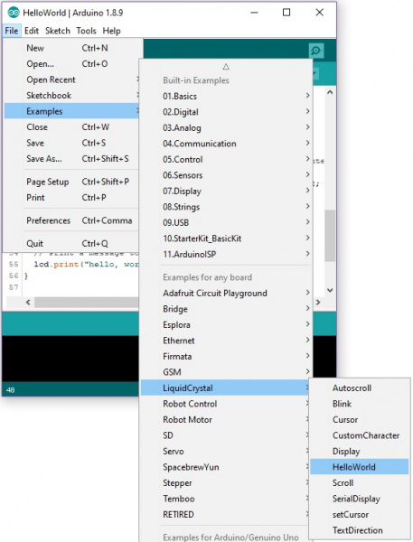
Note: A library is a prebuilt collection of software functions that you can easily include in your code.Open the Arduino IDE, and load the example program: File > Examples > LiquidCrystal > HelloWorld.
Once open, you will need to adjust the pin connections based on your circuit. In this case, we'll need to adjust the pin definitions based on our circuit that we connected earlier. Head to the line where the pins are defined.
language:cconst int rs = 12, en = 11, d4 = 5, d5 = 4, d6 = 3, d7 = 2;LiquidCrystal lcd(rs, en, d4, d5, d6, d7);Then adjust the pin definitions based on your connections.
language:cconst int rs = 13, en = 12, d4 = 11, d5 = 10, d6 = 9, d7 = 8;LiquidCrystal lcd(rs, en, d4, d5, d6, d7);You can also copy and paste the code below. Just make sure to select the correct board (in this case the Arduino/ Genuino Uno) and the COM port that the Arduino enumerated on. Then upload the code to your Arduino.
language:c/*LCD-Hello_world.ino Modified By: Ho Yun "Bobby" Chan SparkFun Electronics Date: 5/22/2019 License: This code is public domain. Demonstrates the use a 16x2 LCD display. The LiquidCrystal library works with all LCD displays that are compatible with the Hitachi HD44780 driver. There are many of them out there, and you can usually tell them by the 16-pin interface. This sketch prints "Hello World!" to the LCD and shows the time since the Arduino was turned on. Hardware Hookup:lCD VSS pin to GNDLCD VCC pin to 5V10kΩ Potentiometer to LCD VO pin (pin 3)LCD RS pin to digital pin 13LCD R/W pin to GNDLCD Enable pin to digital pin 12...LCD D4 pin to digital pin 11LCD D5 pin to digital pin 10LCD D6 pin to digital pin 9LCD D7 pin to digital pin 8LCD-Backlight - Anode to 10KΩ resistor to +5V (optional depending on your LCD)LCD Backlight - K to GND Library originally added 18 Apr 2008 by David A. Mellis library modified 5 Jul 2009 by Limor Fried (http://www.ladyada.net) example added 9 Jul 2009 by Tom Igoe modified 22 Nov 2010 by Tom Igoe modified 7 Nov 2016 by Arturo Guadalupi http://www.arduino.cc/en/Tutorial/LiquidCrystalHelloWorld=https://learn.sparkfun.com/tutorials/basic-character-lcd-hookup-guide*/// include the library code:#include //initialize the library by associating any needed LCD interface pin//with the arduino pin number it is connected toconst int rs = 13, en = 12, d4 = 11, d5 = 10, d6 = 9, d7 = 8;LiquidCrystal lcd(rs, en, d4, d5, d6, d7);void setup() { //set up the LCD's number of columns and rows: lcd.begin(16, 2); //Print a message to the LCD. lcd.print("Hello, world!");}void loop() { //set the cursor to column 0, line 1 //(note: line 1 is the second row, since counting begins with 0): lcd.setCursor(0, 1); // print the number of seconds since reset: lcd.print(millis() / 1000);}After uploading it to your board, a "hello, world!" should appear on the display. The LCD will also display the time in seconds since the Arduino was reset. You should see something similar to the image below. Depending on how you wrote the code, the letter h might be upper or lower case.
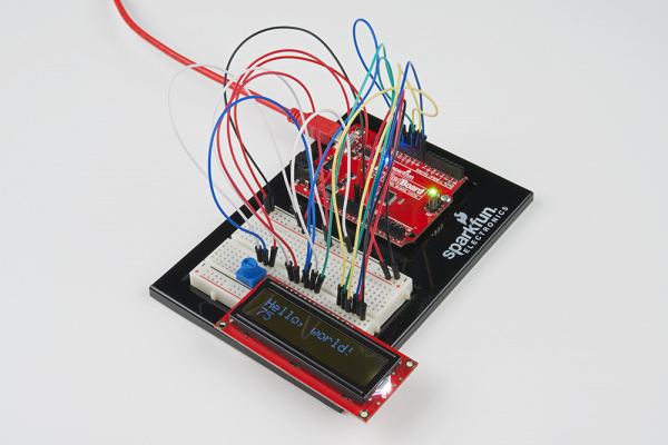
If you see "hello, world!", congratulations! Take a look at the example sketch, and try modifying it to display "hello, your name!" or any other text you'd like. Also, take a look at the other example LiquidCrystal sketches, and the documentation on the Arduino.cc website to see how to write sketches to take advantage of the display. Just make sure to adjust the pin definitions based on how you wired the LCD to your Arduino.
Custom User-Defined GraphicsIf you need to make custom characters, there are a few online tools to generate a user-defined graphics. Check out the link below to create your own custom graphic or use any characters made in the pattern library.
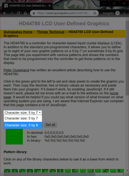
HD44780 LCD User-Defined GraphicsFor simplicity, we'll just use one of the patterns already generated in the library. Let's create an empty heart. First, you'll need to select your character size. The display that we are using in this example is an 8x5 character space. You'll need to select "Character size: 5 by 8" from the drop down menu so that there is 8 rows and 5 columns of pixels.
Then scroll down the webpage and click on the empty heart listed under the Pattern library. You will be presented with values representing the custom character in decimal, hex, and binary.
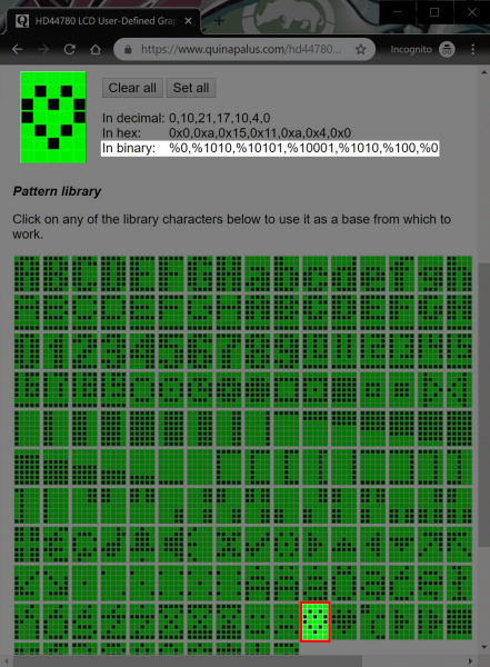
We'll use the binary representation of the empty heart. Each value between the comma represents a slice of the custom character space starting from the top of your character space. A pixel is cleared when the value is 0 and darkened when the value is 1.
language:bash%0,%0,%1010,%10101,%10001,%1010,%100,%0You will need to copy the values and format it in your code. Since we are using an Arduino to control the basic character display, we'll place the values within an array. We'll name this array emptyHeart[]. To make it easier to read and ensure that the pixel is turned off, we will fill in the most significant bits with 0's to the left of the values so that each slice from the custom character space has a size of 1x5. After formating the values, your array should look like the code below in Arduino.
language:cbyte emptyHeart[8] = { B00000, B00000, B01010, B10101, B10001, B01010, B00100, B00000};Congratulations! You have just created a custom character! Repeat the steps for up to 8x custom characters as necessary.
Example CodeNow that we have created a custom user-defined graphic, let's display it on a screen with a message. The example code below loads three custom characters and displays them on the LCD with a message. Copy the code and paste in the Arduino IDE. Select your board (in this case the Arduino/ Genuino Uno) and COM port. Then upload the code to your Arduino.
language:c/*LCD-CustomChar.ino By: Ho Yun "Bobby" Chan SparkFun Electronics Date: May 16th, 2019 License: This code is public domain. Description: Demonstrates the use a 16x2 LCD display with custom user-defined graphic based on the exampleused in the Arduino.cc's Reference Library: createChar(). A message will display with an empty and full heart! Hardware Hookup:lCD VSS pin to GNDLCD VCC pin to 5V10kΩ Potentiometer to LCD VO pin (pin 3)LCD RS pin to digital pin 13LCD R/W pin to GNDLCD Enable pin to digital pin 12...LCD D4 pin to digital pin 11LCD D5 pin to digital pin 10LCD D6 pin to digital pin 9LCD D7 pin to digital pin 8LCD-Backlight - Anode to 10KΩ resistor to +5V (optional depending on your LCD)LCD Backlight - K to GND For more information about using the creatChar() function, make sure to check out the Arduino.cc reference and associated tutorial: https://www.arduino.cc/en/Reference/LiquidCrystalCreateChar https://learn.sparkfun.com/tutorials/basic-character-lcd-hookup-guide*///Include the library code:#include // initialize the library by associating any needed LCD interface pin// with the arduino pin number it is connected toconst int rs = 13, en = 12, d4 = 11, d5 = 10, d6 = 9, d7 = 8;LiquidCrystal lcd(rs, en, d4, d5, d6, d7);//Load custom charcter into CGRAM//Note: Up to 8 characters can be savedbyte smiley[8] = { B00000, B10001, B00000, B00000, B10001, B01110, B00000,};byte emptyHeart[8] = { B00000, B00000, B01010, B10101, B10001, B01010, B00100, B00000};byte fullHeart[8] = { B00000, B00000, B01010, B11111, B11111, B01110, B00100, B00000,};void setup() { //Load a custom character (glyph) for use on the LCD lcd.createChar(0, smiley); lcd.createChar(1, emptyHeart); lcd.createChar(2, fullHeart); //Set up the LCD's number of columns and rows: lcd.begin(16, 2); //Clear the display lcd.clear();}void loop() { //Set the cursor to the 0,0 position (top left corner) lcd.setCursor(0, 0); //Display a message with the custom characters lcd.print("I "); lcd.write(byte(1)); //display custom character related associated with num 1 lcd.print(" SparkFun! "); lcd.write(byte(0)); //display custom character related associated with num 0 delay(1000); //Set the cursor to the 0,0 position (top left corner) lcd.setCursor(2, 0); lcd.write(byte(2)); //display custom character related associated with num 1delay(1000);}After uploading, a message will display with an empty and full heart!
 RGB LED Backlight Control
Previous examples connect the white LED backlight to power. The following example is specifically for those using an LCD with a RGB LED backlight. The only difference between the connection is the LED's backlight on pins 15-18.
Copy and paste the code below. Just make sure to select the correct board (in this case the Arduino/ Genuino Uno) and the COM port that the Arduino enumerated on. Then upload the code to your Arduino.
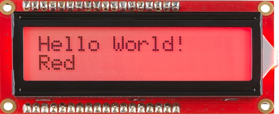
language:c/* LCD-RGB_Hello World.ino By: Ho Yun "Bobby" Chan SparkFun Electronics Date: 5/22/2019 License: This code is public domain. Modified example code of Arduino.cc's Hello World. https://www.arduino.cc/en/Tutorial/HelloWorld Demonstrates the use a 16x2 LCD display with a common cathode RGB LED backlight. The LiquidCrystal library works with all LCD displays that are compatible with the Hitachi HD44780 driver. There are many of them out there, and you can usually tell them by the 16-pin/18-pin interface. This sketch prints "Hello world!" to the LCD, shows the time since the Arduino was last reset, andcontrols the RGB backlight. The backlight displays the primary, secondary, and tertiary colors. Hardware Hookup:LCD VSS pin to GNDLCD VCC pin to 5V10kΩ Potentiometer to LCD VO pin (pin 3)LCD RS pin to digital pin 13LCD R/W pin to GNDLCD Enable pin to digital pin 12....LCD D4 pin to digital pin 11LCD D5 pin to digital pin 10LCD D6 pin to digital pin 9LCD D7 pin to digital pin 8LCD Backlight - K (Common Cathode) to GNDLCD Backlight - Anode-RED to 330Ω to PWM pin 6LCD Backlight - Anode-GREEN to 330Ω to PWM pin 5LCD Backlight - Anode-BLUE to 330Ω to PWM pin 3 Note: You may need to adjust the current limiting resistor and PWM value for the LED depending on the voltage used. Depending on the mixed color, this may result in a lower brightness. https://learn.sparkfun.com/tutorials/basic-character-lcd-hookup-guide*///Include the library code:#include //LED Backlightint ledR = 6;//hardware PWMint ledG = 5;//hardware PWMint ledB = 3; //hardware PWMint redIntensity = 255; //value to adjust since red can be brighter than the other colors depending on the resistor value used//Initialize the library by associating any //needed LCD interface pin with the Arduino pin//number it is connected toconst int rs = 13, en = 12, d4 = 11, d5 = 10, d6 = 9, d7 = 8;LiquidCrystal lcd(rs, en, d4, d5, d6, d7);void setup() { //Set up the LCD's number of columns and rows: lcd.begin(16, 2); //Clear the display lcd.clear(); //Test Colors sequenceTest(); lcd.setCursor(0, 0); //Print a message to the LCD. lcd.print("Hello, world!"); //Turn on backlight for red redON(); lcd.setCursor(0, 1); lcd.print("Red"); delay(1500); lcd.setCursor(0, 1); lcd.print("");}void loop() { // set the cursor to column 0, line 1 // (note: line 1 is the second row, since counting begins with 0): lcd.setCursor(0, 1); // print the number of seconds since reset: lcd.print(millis() / 1000);}void allOFF() { analogWrite(ledR, 0); analogWrite(ledG, 0); analogWrite(ledB, 0);}void allON() { analogWrite(ledR, redIntensity); analogWrite(ledG, 255); analogWrite(ledB, 255);}void redON() { analogWrite(ledR, redIntensity); analogWrite(ledG, 0); analogWrite(ledB, 0);}void roseON() { analogWrite(ledR, redIntensity); analogWrite(ledG, 0); analogWrite(ledB, 128);}void magentaON() { analogWrite(ledR, redIntensity); analogWrite(ledG, 0); analogWrite(ledB, 255);}void violetON() { analogWrite(ledR, 128); analogWrite(ledG, 0); analogWrite(ledB, 255);}void blueON() { analogWrite(ledR, 0); analogWrite(ledG, 0); analogWrite(ledB, 255);}void azureON() { analogWrite(ledR, 0); analogWrite(ledG, 128); analogWrite(ledB, 255);}void cyanON() { analogWrite(ledR, 0); analogWrite(ledG, 255); analogWrite(ledB, 255);}void springgreenON() { analogWrite(ledR, 0); analogWrite(ledG, 255); analogWrite(ledB, 128);}void greenON() { analogWrite(ledR, 0); analogWrite(ledG, 255); analogWrite(ledB, 0);}void chartreuseON() { analogWrite(ledR, 128); analogWrite(ledG, 255); analogWrite(ledB, 0);}void yellowON() { analogWrite(ledR, redIntensity); analogWrite(ledG, 255); analogWrite(ledB, 0);}void orangeON() { analogWrite(ledR, redIntensity); analogWrite(ledG, 51); analogWrite(ledB, 0);}void sequenceTest() { lcd.setCursor(0, 0); lcd.print("Backlight Color"); lcd.setCursor(0, 1); //set the cursor to the second row, 1st position lcd.print(" ");//clear 2nd row lcd.setCursor(0, 1); //set the cursor to the second row, 1st position lcd.print("Red"); redON();//good delay(1500); lcd.setCursor(0, 1);//set the cursor to the second row, 1st position lcd.print(" ");//clear 2nd row lcd.setCursor(0, 1);//set the cursor to the second row, 1st position lcd.print("Rose"); roseON(); delay(1500); lcd.setCursor(0, 1);//set the cursor to the second row, 1st position lcd.print(" ");//clear 2nd row lcd.setCursor(0, 1);//set the cursor to the second row, 1st position lcd.print("Magenta"); magentaON();//good delay(1500); lcd.setCursor(0, 1);//set the cursor to the second row, 1st position lcd.print(" ");//clear 2nd row lcd.setCursor(0, 1);//set the cursor to the second row, 1st position lcd.print("Violet"); violetON(); delay(1500); lcd.setCursor(0, 1);//set the cursor to the second row, 1st position lcd.print(" ");//clear 2nd row lcd.setCursor(0, 1);//set the cursor to the second row, 1st position lcd.print("Blue"); blueON();//good delay(1500); lcd.setCursor(0, 1);//set the cursor to the second row, 1st position lcd.print(" ");//clear 2nd row lcd.setCursor(0, 1);//set the cursor to the second row, 1st position lcd.print("Azure"); azureON();//good delay(1500); lcd.setCursor(0, 1);//set the cursor to the second row, 1st position lcd.print(" ");//clear 2nd row lcd.setCursor(0, 1);//set the cursor to the second row, 1st position lcd.print("Cyan"); cyanON();//good delay(1500); lcd.setCursor(0, 1);//set the cursor to the second row, 1st position lcd.print(" ");//clear 2nd row lcd.setCursor(0, 1);//set the cursor to the second row, 1st position lcd.print("Spring Green"); springgreenON();//good delay(1500); lcd.setCursor(0, 1);//set the cursor to the second row, 1st position lcd.print(" ");//clear 2nd row lcd.setCursor(0, 1);//set the cursor to the second row, 1st position lcd.print("Green"); greenON();//good delay(1500); lcd.setCursor(0, 1);//set the cursor to the second row, 1st position lcd.print(" ");//clear 2nd row lcd.setCursor(0, 1);//set the cursor to the second row, 1st position lcd.print("Chartreuse"); chartreuseON(); delay(1500); lcd.setCursor(0, 1);//set the cursor to the second row, 1st position lcd.print(" ");//clear 2nd row lcd.setCursor(0, 1);//set the cursor to the second row, 1st position lcd.print("Yellow"); yellowON();//good delay(1500); lcd.setCursor(0, 1);//set the cursor to the second row, 1st position lcd.print(" ");//clear 2nd row lcd.setCursor(0, 1);//set the cursor to the second row, 1st position lcd.print("Orange"); orangeON();//good delay(1500); lcd.setCursor(0, 1);//set the cursor to the second row, 1st position lcd.print(" ");//clear 2nd row lcd.setCursor(0, 1);//set the cursor to the second row, 1st position lcd.print("White"); allON(); delay(1500); lcd.setCursor(0, 1);//set the cursor to the second row, 1st position lcd.print(" ");//clear 2nd row lcd.setCursor(0, 1);//set the cursor to the second row, 1st position lcd.print("LEDs Off"); allOFF(); delay(1500); lcd.setCursor(0, 0);//set the cursor to the second row, 1st position lcd.clear();//Clear the display}After uploading, you will notice the same "Hello, world!" and time since the Arduino was last reset in the first example. The only difference is that the current color of the backlight will be printed as it cycles through each of the primary, secondary, and tertiary colors. You should see something similar to the image below.
 Troubleshooting and FAQThe Screen is Blank or Flickering
If no message appears, the contrast may need to be adjusted. To do this, turn the potentiometer until "hello, world!" until you can view characters on the screen. Adjust the contrast by twisting the potentiometer. If it’s incorrectly adjusted, you won’t be able to read the text clearly. Also, check the potentiometer and make sure it's connected correctly. If you still don't see anything, double-check your wiring to ensure that the wires are fully connected. Also, check your solder joints to ensure that there is a sufficient connection.
Not Working At AllDouble check the circuit's wiring. There are a lot of wires in this circuit, and it's easy to mix up one or two.
Rectangles in First Row and Random CharactersIf you see 16x rectangles (like “█”) or random characters on the first row, it may be due to the jumper wires being loose on the breadboard. This is normal and can happen with other LCDs wired in parallel with a microcontroller. Make sure that the wires are fully inserted into the breadboard, then try pressing the reset button and adjusting the contrast using the potentiometer. Also, make sure that the defined pins match your current setup.
 A display that needs the contrast adjusted. Note the white rectangles.Still Not Working?
Jumper wires unfortunately can go "bad" from getting bent too much. The copper wire inside can break, leaving an open connection in your circuit. If you are certain that your circuit is wired correctly and that your code is error-free and uploaded but you are still encountering issues, try replacing one or more of the jumper wires for the component that is not working. You may need to rework the solder joints for a secure connection.
Can I Connect a Basic Character LCD to the ESP8266 Thing Development Board?Yes. However, the ESP8266 Thing Dev is 3.3V. You'd have to use two logic level converters (like the four channel bidirectional logic level converter) to convert 6x pins at a minimum if you were using a 5V basic character display. That's a lot of wires. Make sure to avoid using pin D0, D16, Tx, and Rx. There are issues displaying characters using those pins since they are tied to other functions such as the reset or deep sleep. The pin definitions can be defined as the following.
language:cconst int rs = 2, en = 14, d4 = 5, d5 = 4, d6 = 13, d7 = 12;LiquidCrystal lcd(rs, en, d4, d5, d6, d7);The hookup should look similar to the following diagrams.
 Resources and Going Further
Now that you've successfully got your basic character LCD up and running, it's time to incorporate it into your own project! For more information, check out the resources below:
Schematic (JPG) - Old application circuit in a schematic view for a 16x2 basic character LCD.DatasheetsBasic LCD Datasheet (PDF)Extended LCD Datasheet (PDF)HD44780 (PDF)OLD SIK Guide LCD Example (PDF) - Old SIK example for Arduino with insert.Custom Character Generator (ZIP)Online Custom Character GeneratormBed Example CodeAVR Example CodeArduino Reference Library: LiquidCrystalNeed some inspiration for your next project? Check out some of these related tutorials to use the display in javascript, create your own game using custom characters, or display sensor data on your screen.
Experiment Guide for the Johnny-Five Inventor's Kit Use the Tessel 2 and the Johnny Five Inventors kit to explore the world of JavaScript enabled hardware through 14 awesome experiments!FavoritedFavorite8Endless Runner Game We make a simple side-scrolling endless runner game using parts from the SparkFun Inventor's Kit v4.0.FavoritedFavorite6SparkFun Inventor's Kit Experiment Guide - v4.0 The SparkFun Inventor's Kit (SIK) Experiment Guide contains all of the information needed to build all five projects, encompassing 16 circuits, in the latest version of the kit, v4.0a. FavoritedFavorite8Instead of using a parallel interface, you can also try using a serial connection to reduce the amount of wires.
PIC-Based Serial Enabled Character LCD Hookup Guide The PIC-based serial enabled character LCD backpack is a simple and cost effective solution for interfacing to character Liquid Crystal Displays (LCDs) based on the HD44780 controller. The backpack simplifies the number of wires needed and allows your project to display all kinds of text and numbers.FavoritedFavorite4AVR-Based Serial Enabled LCDs Hookup Guide The AVR-based Qwiic Serial Enabled LCDs are a simple and cost effective solution to include in your project. These screens are based on the HD44780 controller, and include ATmega328P with an Arduino compatible bootloader. They accept control commands via Serial, SPI and I2C (via PTH headers or Qwiic connector). In this tutorial, we will show examples of a simple setup and go through each communication option.FavoritedFavorite14Or check out this activity if you are an educator.
SIK LCD Tutorial Activity July 23, 2016SIK LCD Tutorial simplifies the wiring and usage of the parallel LCD module that is included in the SIK.FavoritedFavorite2ShareUse this URL to share: Share on Tumblr Submit to reddiShare on TwitterShare on Facebook Pin It